Use in Project Development
Once an ITS project has been funded and implementation begins, there is a natural tendency to focus on the programmatic and technical details of the project to be implemented and lose sight of the broader regional context for the project. Using the regional ITS architecture as a basis for project implementation provides this regional context. It provides each project sponsor the opportunity to view their project in the context of surrounding systems. It prompts the sponsor to think about how their project fits within the overall transportation vision for the region. It identifies the integration opportunities that should be considered and provides a head start for the systems engineering analysis that is required for ITS projects.
 Due
to these potential benefits, the federal Regulation/Policy on Architecture and
Standards requires the regional ITS architecture to be used for project
implementation. Specifically, 23 CFR 940.11.c.1 and FTA National ITS
Architecture Policy Section 6.c.1 require identification of the portion of the
regional ITS architecture that is implemented by each ITS project.
Due
to these potential benefits, the federal Regulation/Policy on Architecture and
Standards requires the regional ITS architecture to be used for project
implementation. Specifically, 23 CFR 940.11.c.1 and FTA National ITS
Architecture Policy Section 6.c.1 require identification of the portion of the
regional ITS architecture that is implemented by each ITS project.
Project Development Approaches
As described in Use for Programming, transportation projects are identified and funded through transportation planning and programming/budgeting phases. Funded projects are then implemented using a project development process that will vary with the type of project.
Traditional Project Development Approach
ITS projects that install field equipment, such as the installation of variable message signs, use a process that is very close to the traditional project development process shown in the Figure below. ITS projects that include hardware and software development and integration will require additional systems engineering analyses that can be thought of as extensions to the traditional project development process.
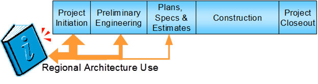
Traditional Project Development Approach
While project development processes vary from state to state and from organization to organization in each state, the transportation project development process tends to have the same major steps.
- Project Initiation – At this step, the project manager is identified, the project team is assembled, and the project development is planned. A high-level definition of the project is developed, costs are estimated, and the required forms and checklists are completed to garner approval for the project from the sponsoring and funding agency(ies). For FHWA and FTA, this is a critical point in the process where approval to proceed is given and federal funds are obligated. For the project sponsor, this is the best opportunity to consider integration opportunities and use the regional ITS architecture to inform the initial project scoping and definition. The regional ITS architecture can be used to define the project's scope at this step – identifying the involved stakeholders and high-level roles and responsibilities, the portion of the regional ITS architecture to be implemented, and where in the project sequencing the project is identified.
- Preliminary Engineering – In the traditional capital project development process, environmental, right-of-way, and other studies are performed depending on the type of project. These studies result in better understanding of the project requirements and constraints. ITS projects that include a construction component will require these same studies as well as additional engineering analyses to fully specify the project requirements for the ITS portion of the project. The regional ITS architecture can contribute to these preliminary engineering analyses since it includes high-level functional requirements and interface definitions that can be used as a starting point. Note that from a federal aid perspective, "preliminary engineering" also includes PS&E. PS&E is split out separately here to differentiate between requirements and design steps in the traditional development process.
- Plans, Specifications, and Estimates – The detailed design for the project, complete with detailed project specifications, estimates of material needs, and associated costs are documented. In a traditional construction project, this process step provides companies with all the information they need to develop an accurate bid. Construction elements within an ITS project will also require traditional design documentation (i.e., layout sheets, plan and elevation views, cross-section details, etc.). Design documentation is also required for the hardware and software components in an ITS project, but it takes the form of high-level design, interface specification, and detailed hardware and software specifications. The architecture provides some input at this step, including information about ITS standards that may be relevant to the project.
- Construction – The project is built. For a traditional transportation project, this is construction of the actual physical improvement. For an ITS project, this includes the implementation of the actual hardware, software, and enabling products (e.g., manuals, operating procedures, and training). This step also includes inspection of the physical improvement(s) and integration and testing of the implemented system(s).
- Project Closeout – After final inspection/testing, the completed project is accepted, as-built plans are created, and a project history file is completed.
As shown, the best opportunity for use of the regional ITS architecture is early in the development process when the project is initiated and preliminary engineering is performed. The architecture is most valuable as a scoping tool that allows a project to be broadly defined and shown in a regional context. In later steps, when the project scope is firmly established and the project is defined in increasing detail, there is less opportunity to use the high-level definitions included in the regional ITS architecture. More detailed guidance for using the regional ITS architecture at each step in the project development process is defined on the rest of the tabs.
Systems Engineering for ITS Projects
Systems engineering is an interdisciplinary approach for systems development that is used in many different industries because it contributes to project success. Every ITS project manager wants a successful project, where "success" is measured by:
- the cost and schedule performance of the project
- how well the implemented system ultimately satisfies the needs of the people who use it
The primary benefit of systems engineering is that it can reduce the risk of schedule and cost overruns and increase the likelihood that the system will meet the user's needs. Other frequently cited benefits include:
- better system documentation
- better stakeholder participation
- shorter project cycles
- resilient systems that can evolve without major redesign
- increased component reuse
- more predictable outcomes
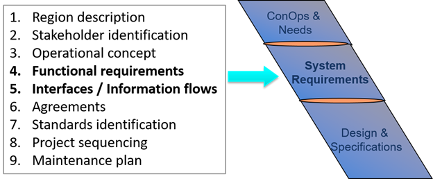
The Figure below shows an approach to systems engineering known as the "Vee" model that graphically depicts the systems engineering approach for the life cycle of a system. This model was developed to help agencies perform systems engineering for ITS projects. The core systems engineering project development processes that are the focus of this section are enclosed in a dashed box at the center of the "Vee".
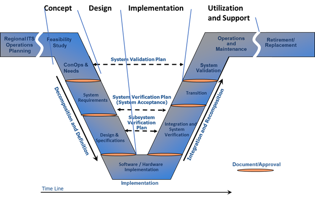
The "Vee" Diagram Approach to Systems Engineering
The "Vee" diagram also includes two wings that show the broader project lifecycle from initial project identification at the beginning of the lifecycle through system retirement or replacement at the end of the lifecycle. An important aspect of the systems engineering process is that the entire project lifecycle is considered during project development.
A systems engineering approach requires up-front planning and system definition so that the project requirements are identified and documented before technology choices are made and the system is implemented. On the left side of the diagram, the system definition progresses from a general user view of the system to a detailed specification of the system design. As development progresses, a series of documented baselines are established that support the following steps. For example, a consensus concept of operations supports system requirements development. A baseline set of requirements then supports design and, in many cases, procurement. The hardware and software are implemented as shown at the bottom of the diagram then the components of the system are integrated, tested, and verified in iterative fashion on the right. Ultimately, the completed system is validated to measure how well it meets the user's needs. Significantly, there is traceability from one step to the next and also traceability between steps on both sides of the diagram since the system definition that is generated on the left is used to verify the system on the right. The user needs that are identified in the very first step of the process are used to validate the completed system as part of system validation.
 Following
a system engineering approach during implementation of ITS projects is a key
requirement of the Regulation/Policy. For resources on systems engineering,
refer to FHWA's Facilitating Integrated ITS Deployment Program page at https://ops.fhwa.dot.gov/int_its_deployment/index.htm.
In addition, the FHWA
Systems Engineering for ITS, website – https://ops.fhwa.dot.gov/seits/, is another key resource for this topic.
Following
a system engineering approach during implementation of ITS projects is a key
requirement of the Regulation/Policy. For resources on systems engineering,
refer to FHWA's Facilitating Integrated ITS Deployment Program page at https://ops.fhwa.dot.gov/int_its_deployment/index.htm.
In addition, the FHWA
Systems Engineering for ITS, website – https://ops.fhwa.dot.gov/seits/, is another key resource for this topic.
Using ITS Architectures to Support Systems Engineering
The regional ITS architecture provides context for ITS projects. By using the regional ITS architecture as a starting point, the steps taken by each project will be on the path to the larger objectives set forth in the long range transportation plan. The ARC-IT tools, RAD-IT and SET-IT, allow the transportation planner and project developer to use ARC-IT to create their own regional ITS architecture and project architectures, respectively. These tailored architectures are not just references: they are structured descriptions of services provided, relationships required, and items to be deployed, operated, maintained and managed. As responsibility shifts from the planner to the project developer, ARC-IT tool use shifts from RAD-IT to SET-IT.
FHWA/FTA Requirements
US
DOT recognized the potential benefit of a systems engineering approach and
included requirements for a systems engineering analysis for ITS projects in
the FHWA Regulation/FTA Policy. The Regulation/Policy requires a system
engineering analysis (SEA) to be performed for ITS projects that are funded
through the highway trust fund. The Regulation/ Policy says the following 7
items should be included in the SEA:
(1) Identification of portions of the regional ITS architecture being implemented;
(2) Identification of participating agencies roles and responsibilities;
(3) Requirements definitions;
(4) Analysis of alternative system configurations and technology options to meet requirements;
(5) Procurement options;
(6) Identification of applicable ITS standards and testing procedures; and
(7) Procedures and resources necessary for operations and management of the system
Relating the systems engineering analysis requirements in the Regulation/Policy we see a primary focus on the first few steps or the typical systems engineering approach or left-hand side of the "Vee" diagram, as shown in the figure below.
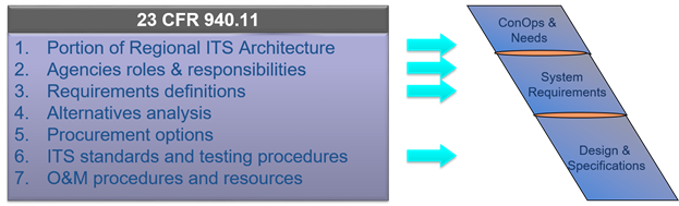
Regulations and Systems Engineering
Regional Architecture support to SE Processes
Regional ITS Architectures contain a variety of information relevant to fulfilling the CFR 940.11 SEA requirements, or more generally, information relevant to the steps in a systems engineering process. The extent with which a Regional ITS Architecture will support SEA or the SE processes is a function of the details contained within the particular architecture. These details can vary from region to region depending on how they have chosen to address the requirements of CFR 940.11.
The following components of the Regional ITS Architecture can be used to develop these SEA requirements:
- Portion of the Regional ITS Architecture (addressed by the project): Stakeholders, Inventory, Information flows, and service packages are the basic components that can be mapped to the project. If the Regional ITS Architecture has Project ITS Architectures defined for its projects, then the relevant components for the project will be defined either in the RAD-IT file or on a website version of the architecture.
- Agencies Roles and Responsibilities: A subset of the Operational Concept of the Regional ITS Architecture can be selected to address this requirement. Again, if project ITS architectures are created, they may already have selected the subset of the overall Roles and Responsibilities relevant to the project.
- Functional Requirements: The functional areas (or functional requirements) selected for the elements that are a part of the project can be used as a starting point to address this requirement. See Project ITS Architectures and the SE Processes for additional details about how creating a more detailed project architecture using SET-IT can provide additional support to the definition of functional requirements.
- ITS Standards and Testing Procedures: The Regional ITS Architecture contains a mapping of standards to information flows, so that selection of a set of information flows for the project can result in creating a list of relevant ITS standards for the project. See Project ITS Architectures and the SE Processes for additional details about how creating a more detailed project architecture using SET-IT can provide additional support for the development of communications profiles for the information flows of the project.
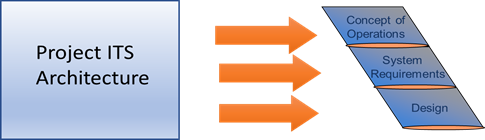
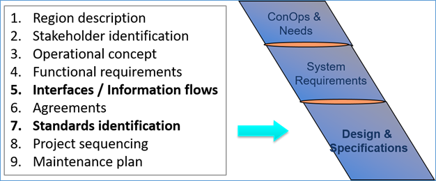
The Regional ITS Architecture provides support to the use of the Systems Engineering process for development of an ITS project. As shown in the figure below, the architecture can provide support to the three development steps on the left side of the Vee.
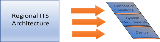
Using the Architecture to Support Systems Engineering
The following components of the Regional ITS Architecture can be used to develop these SE steps:
- Concept of Operations: Stakeholder definitions, Roles and Responsibilities, and service packages, and agreements. Further information about how an architecture can support the ConOps development is at Use in Concept of Operations Development.
- System Requirements: Functional Requirements. Further information about how an architecture can support the Requirements development is at Use in System Requirements Development.
- Design: Project ITS Architecture developed in RAD-IT, standards definition. Further information about how an architecture can support the Design is at Use in Project Design.
Since every regional ITS architecture is a bit different, each architecture's utility in supporting the systems engineering process will vary. For example, regional ITS architectures that include tailored functional requirements will provide a better starting point for project system requirements definition than regional ITS architectures that have just a few generic requirements. The region should take a candid look at the utility of their regional ITS architecture in the project implementation process and refine it over time so that it provides the best possible support for each project sponsor's systems engineering process.
Project ITS Architectures and the SE Processes
A project ITS architecture contains similar components to a regional ITS architecture, except the scope of it is a single ITS project. There are two ways to develop a project ITS architecture:
- As part of a regional ITS architecture development, by creating projects within the RAD-IT file
- As an independent, more detailed architecture created in SET-IT.
A project ITS architecture can support to the use of the Systems Engineering process for development of an ITS project. As shown in the figure below, the architecture can provide support to the same three development steps on the left side of the Vee that regional ITS architectures support.
Using Project Architectures to Support Systems Engineering
The following components of the project ITS architecture can be used to develop these SE steps:
- Concept of Operations: Stakeholder definitions, Roles and Responsibilities, and service packages, and agreements. Further information about how a project ITS architecture can support the ConOps development is at Use in Concept of Operations Development.
- System Requirements: Functional Requirements. Further information about how a project ITS architecture can support the Requirements development is at Use in System Requirements Development.
- Design: Project ITS Architecture developed in RAD-IT or SET-IT, standards definition. Further information about how a project ITS architecture can support the Design is at Use in Project Design.
For project ITS architectures defined in RAD-IT, the type of information the architecture provides is similar to what the regional ITS architecture provides, since in that case the project ITS architecture is really a subset of the regional ITS architecture. In the case of a project ITS architecture developed in SET-IT, there will be additional details to be used to support each of the three SE steps, which are defined in the pages referenced above.
Mapping Your ITS Project to the Regional ITS Architecture
In order to use the regional ITS architecture to support project development, the portion of the regional ITS architecture that will be included in the project must be identified. This is a key step in architecture use because this is when the ITS project will be viewed in the broader context of the regional ITS architecture. This is when the services, functionality, and integration opportunities envisioned in the region are reviewed and considered as the basic scope of the project is defined. This step is also required to meet the FHWA Regulation/FTA Policy. While the components that should be identified as part of this "subset" are not specified by the Regulation/Policy, the following components, taken together, precisely define the scope of the project in terms of the regional ITS architecture:
- Service Packages
- Inventory Elements
- Information Flows
These components define the system(s) that will be created or impacted by the project, the services that will be implemented, and the interfaces that will be added or updated.
If integration opportunities are to be considered, the regional ITS architecture should be used as early in the project development lifecycle as possible. The architecture should be reviewed before firm project cost estimates are established, while there is still opportunity to adjust the scope to consider the functionality and interfaces identified in the regional ITS architecture. This opportunity may occur before or after programming/budgeting, depending on how specifically the ITS project is defined in the TIP/STIP or other programming/budget document.
Finding the Right Components
It can be difficult to find the components that apply to a project, particularly if the Project Team is unfamiliar with the regional ITS architecture. The best approach for identifying the portion of the regional ITS architecture for a particular project will vary since each regional ITS architecture is defined a bit differently. There are a few logical entry points to the regional ITS architecture that may be of use to the Project Team – chances are that one of these approaches will work best in your region.
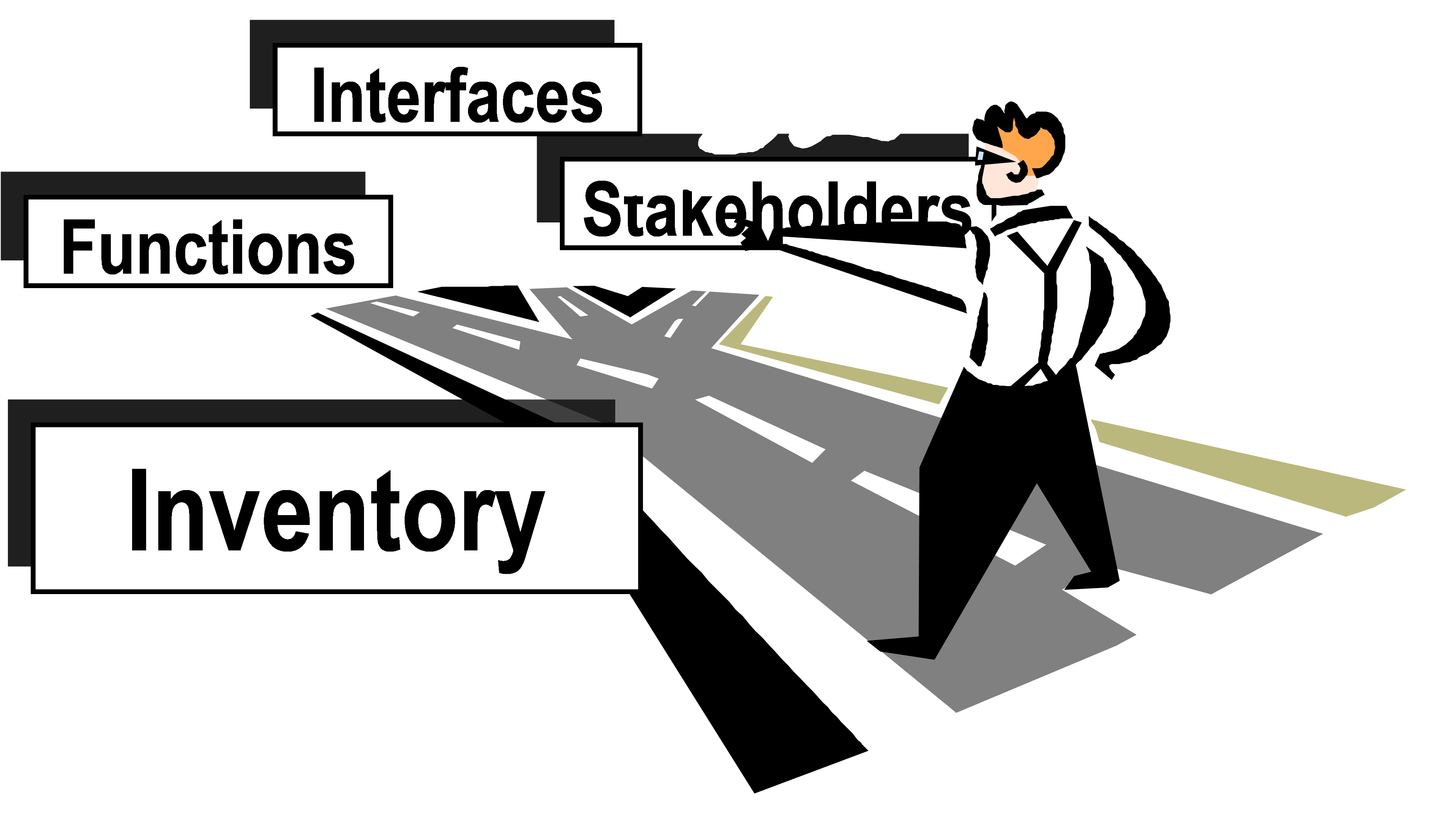
Shown below is a diagram, shown earlier in the discussion on regional architectures, that contains all the components for an ITS architecture and shows how each component is connected to each other.
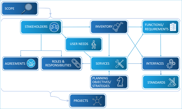
Components of an ITS Architecture
Start with Project Sequencing
The connection between the regional ITS architecture and ITS projects is clearest if the project to be implemented is identified in the project sequencing portion of the regional ITS architecture website or documentation. If the project is identified and explicitly related to the regional ITS architecture in the project sequencing section, then this is probably the best entry point for the Project Team to use. If the project is not included in the project sequencing documentation, then feedback should be provided to the Architecture Owner so that the architecture can be updated to reflect the range of projects that are actually being implemented in the region.
On the architecture website there is usually a project tab that provides some set of information relating the project to the architecture. The information provided on the website likely includes the three components mentioned above. The information may contain a precise definition of the portions of the regional ITS architecture relevant to the project. If not (say it contains only the service package, but not the information flows), then a further customization of the information from the architecture will be needed. If the projects are listed in a document, it likely provides a mapping to service packages, which can serve as an entry point to the architecture as described below.
Start with Transportation Services
If the project is not directly defined on the website, then service packages are an excellent way to begin to isolate the portion of the regional ITS architecture that applies to the project. By identifying the service that the project performs and finding this service in the list of service packages included in the regional ITS architecture, the portions of the architecture related to that service can be identified and then tailored for the project. Note that in most cases, the service package will have to be further refined to precisely match the scope of the project.
Other Starting Points
Depending on the architecture documentation, the Project Team could locate the target system(s) in the list of inventory elements or identify the stakeholder(s) associated with the project in the list of stakeholders. Depending on the linkages in the architecture documentation, one of these entry points can be used to find the portion of the regional ITS architecture that is most relevant to the project to be implemented.
 In order
to facilitate use by numerous Project Teams, each region should define a
roadmap for architecture use that takes advantage of the strengths of their
specific regional ITS architecture. The roadmap should identify the best entry
point(s), e.g., Service Packages, Project Sequencing, Inventory Elements, etc.,
for that architecture, how to locate the relevant item in the list, and how to
navigate to other related items in the architecture documentation.
In order
to facilitate use by numerous Project Teams, each region should define a
roadmap for architecture use that takes advantage of the strengths of their
specific regional ITS architecture. The roadmap should identify the best entry
point(s), e.g., Service Packages, Project Sequencing, Inventory Elements, etc.,
for that architecture, how to locate the relevant item in the list, and how to
navigate to other related items in the architecture documentation.
Considering Additional Integration Options
In almost every case, the regional ITS architecture will identify integration opportunities that will not be included in the current project. Integration options may be deferred for many reasons – agencies on both sides of the interface may not be ready, there may not be sufficient funding or time available to implement everything, supporting infrastructure may not yet be completed, a necessary standard may not be available, implementing too much at once may incur too much complexity/risk, etc.
It is important to explore these integration opportunities so that they are accounted for and supported in the project design, even though they may not be implemented with that specific project. The ultimate goal is to make ITS deployment as economical as possible by considering how this project will support future projects over time. To support this goal, future integration options that may impact the project design should be identified and considered in the project development. For example, additional stakeholders may be involved in the current project to ensure that future requirements are identified and factored into the current project design.
Example Output
The subset of the regional ITS architecture that is included in the project can be shown on a webpage as shown in the example from the Bay Area Architecture below, which shows stakeholders, elements, service packages and information flows for the project.
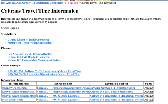
Example Project Information from Bay Area ITS Architecture
 It is a
good idea to include additional interfaces that are closely related to the
project, as shown in the previous example. This gives some context for the
project and conveys information to the project team about how this project will
fit with other future projects. Where this is done, the documentation should be
clear about the subset that is actually included in the current project. It is
also important not to include too much additional information – the goal is to
include only components that are in some way relevant to this particular
project, particularly those that may influence project design decisions.
It is a
good idea to include additional interfaces that are closely related to the
project, as shown in the previous example. This gives some context for the
project and conveys information to the project team about how this project will
fit with other future projects. Where this is done, the documentation should be
clear about the subset that is actually included in the current project. It is
also important not to include too much additional information – the goal is to
include only components that are in some way relevant to this particular
project, particularly those that may influence project design decisions.
Use in Concept of Operations Development
A Concept of Operations describes the operation of the system being developed from the various stakeholder viewpoints in a form that each project stakeholder can understand. It documents the system objectives, user needs, the environment the system will operate in and operational scenarios for the system operation. For additional information about this topic see the Concept of Operations page on the FHWASystems Engineering for ITS website (https://ops.fhwa.dot.gov/seits/sections/section3/3_3_5.html)..
Regional ITS Architecture Use in Con Ops Development
The components of the regional ITS architecture provide a high-level description of the ITS systems in the region, which can often be directly incorporated into a project ConOps. Several of the regional ITS architecture components can be used, as shown in the figure below, which relates the regional architecture to a typical outline for a ConOps based on one of the industry standards for a ConOps, American National Standards Institute (ANSI)/ American Institute of Aeronautics and Astronautics (AIAA) standard G-043-1992. The ANSI standard is the basis for the FHWA Systems Engineering Model Documents. The ConOps for an ITS project should include this information and many more details specific to the project as described in the following paragraphs.
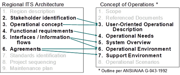
Regional ITS Architecture Use for Concept of Operations
Stakeholder Identification
A ConOps should describe the system from the perspective of each stakeholder. The relevant stakeholders that are identified in the regional ITS architecture are a good starting point for the list of stakeholders considered in the ConOps. The Project Team may need to add stakeholders or provide additional specificity for selected stakeholders.
Operational Concept
The agency roles and responsibilities are a part of the User Oriented Operational Description section of the ConOps. These roles and responsibilities can be derived from the operational concept that is included in the regional ITS architecture. This operational concept can serve as a starting point for a more detailed definition of the operational roles that are described in the ITS Project ConOps.
The specification of participating agencies' roles and responsibilities is also a required part of the Systems Engineering Analysis as specified in the Regulation/Policy.
Functional Requirements
The high-level functional requirements that are defined in the regional ITS architecture are frequently defined at a level that is commensurate with the operational needs that should be defined in the ConOps. The operational needs that are defined in the ConOps then provide a basis for the project requirements that are defined later in the systems engineering process. The high-level requirements from the regional ITS architecture can be included in the ConOps and modified and expanded as necessary so they represent the operational needs of the specific project.
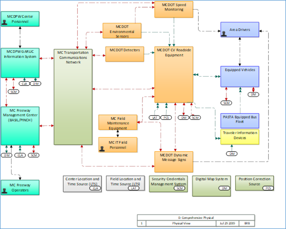
Interfaces / Information Flows
In the System Overview section the ConOps includes a high-level project description that is normally supported by a high-level system block diagram. This system description can be based on the interfaces and information flows that are extracted from the regional ITS architecture. Depending on the regional ITS architecture and the nature of the project, the project description that is derived from the regional ITS architecture should be refined so that it is as easy to understand as possible in the ConOps. Some regional ITS architectures connect each project to service packages which have diagrams that can be referenced as part of the ConOps.
The relationship to the regional ITS architecture that is developed for each project should also be included in the ConOps. If the ANSI/AIAA outline is used for the ConOps, this information would logically fit in the Operational Environment paragraph, or the outline could be tailored and a specific "Relationship to the Regional ITS Architecture" paragraph could be added.
Agreements
System integration is as much an institutional challenge as it is a technical system engineering exercise. The regional ITS architecture identifies regional agreements that may be relevant to the project. Necessary agreements should be identified for the project and listed in either the project plan or the ConOps. If the ANSI/AIAA outline is used, the list of agreements would logically fit in either the operational environment or support environment sections. The location of the list of agreements isn't so important as long as it is included in the document and the project plan addresses the creation of the necessary agreements.
Project ITS Architecture Use in Con Ops Development
A project ITS architecture, created using the SET-IT tool, can provide significant additional information, beyond that described above from a regional ITS architecture, that can support the development of a ConOps for an ITS project. The tool contains several templates to generate a ConOps, based on either the International Standards Organization (ISO) / International Electrotechnical Commission (IEC)/ Institute of Electrical and Electronics Engineers (IEEE) standard 29148 or the ANSI/AIAA standard outline. Each outline can be customized for a specific project. The tool will generate the following information which can be used to populate key sections of the ConOps:
- User Needs, derived from the user needs statements associated with each service package to form a portion of the chapter on Justification for Change
- Physical View of the project which can be used to populate the chapter on Description of the Proposed System. The Physical View can include the following tool outputs:
- Physical Interconnect Diagram which defines the interconnects for the entire project. The information includes a diagram (An example from the sample project in SET-IT is shown below), as well as tables that describe the elements, the physical interconnects.
- Physical Context Diagrams. These provide the context for a system element by showing all of the interfaces for that element.
- Enterprise View of the project, which describes the enterprises or stakeholders and their relationships between each other. The enterprise view is based on the roles those organizations play within the transportation environment and is also included in the ConOps chapter on Description of the Proposed System. The Enterprise View can include the following tool outputs
- Tables that define the roles the Stakeholders perform
- Enterprise diagram that show the relationships between the stakeholders
- Enterprise Context Diagrams, which provide the context for a system stakeholder by showing all of the interfaces for that stakeholder.
- Operational Scenarios using Service Package diagrams annotated with sequences in one or more scenarios involving those services.
Interconnect diagram for Sample Project in SET-IT
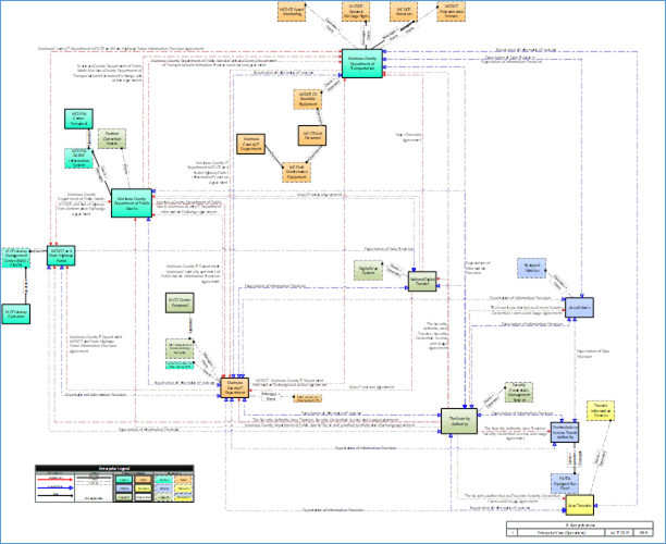
Enterprise Diagram for Sample Project
Use in System Requirements Development
One of the most important attributes of a successful project is a clear statement of requirements that meet the stakeholders' needs. For more information about the requirements development process, see the Systems Engineering for ITS Website. Both Regional ITS Architectures and Project ITS Architectures can provide an input to this requirements development as described below.
Regional ITS Architecture Use in Requirements Development
The functional requirements and interfaces defined in the regional ITS architecture can be used to support system requirements definition as shown in the figure below. The functional requirements associated with the inventory element(s) that are included in the project can be scanned to identify requirements that cover the required functionality for the project. These functional requirements can be one of the inputs to system requirements definition. In addition to the functional requirements, the project interfaces that are identified in the regional ITS architecture should also be supported by system requirements associated with each interface.
Architecture Use in System Requirements Development
Of course, the project's system requirements should be defined in greater detail than the high-level functional requirements that are included in the regional ITS architecture. The system requirements should also address performance, development, operations and maintenance, and other requirements that are typically not included in a regional ITS architecture as shown in the figure below. While the requirements included in the regional ITS architecture are only a starting point, it is better to start with these requirements than it is to start from scratch. By starting with the regional ITS architecture requirements, the project team can get a head start and also maintain continuity between the regional ITS architecture and the region's projects.
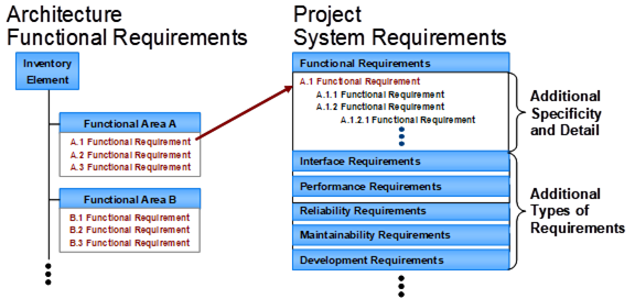
Project System Requirements Analysis
Requirements definitions are a
required part of the Systems Engineering Analysis as specified in the
Regulation/Policy, 23CFR940.11(c)3.
The functional requirements associated with the project may be extracted and used as shown in the excerpt of requirements associated with the Statewide DMS project from the New Mexico Statewide ITS Architecture shown in the figure below. These are the requirements associated with the DMS devices.
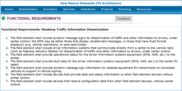
DMS Project Functional Requirements (Partial List)
Each of these requirements from the regional ITS architecture would then be expanded into detailed functional requirements. For example, the single requirement to control the DMS signs that is included in the regional ITS architecture could be a high-level requirement that is expanded into many requirements for message definition, message management, message display, message scheduling, and message prioritization.
Project ITS Architecture Use in Requirements Development
A project ITS architecture defined in SET-IT contains a set of functional requirements that can be used to support project requirements development. Depending on the details of the project architecture, the requirements contained in SET-IT may be similar in level of detail to those in the regional ITS architecture used as the starting point for the development of the project architecture, but SET-IT does include the possibility of creating a project architecture that is more detailed than the regional ITS architecture in terms of elements and interfaces defined for the project. If a greater level of detail in architecture definition is created then the project may provide a more detailed set of requirements to consider as part of project requirements development. The figure below shows a portion of the Element Requirements page from the sample project in SET-IT.
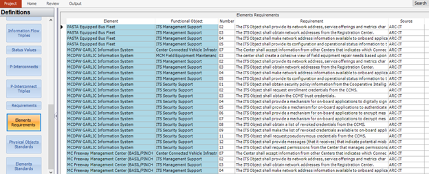
Element Requirements Page from SET-IT
In addition to the functional requirements derived from ARC-IT (in the example above), the SET-IT based project architecture can provide two additional sources of requirements:
- Interface requirements taken from the interfaces and information flows in the physical view
- Requirements related to the definition of standards to be used on the project's interfaces. SET-IT provides a detailed view of the communication protocols that can be used to provide the information exchanges essential to the project.
While these sources are not specifically defined as requirements (e.g. written as shall statements as shown above), the interfaces and standards requirements can be developed from the information contained in the project architecture.
Use in Project Design
Project design is created based on the system requirements and in a systems engineering process is usually defined at two levels. The first level, high-level design, defines the overall framework for the system; the subsystems of the system are identified and decomposed further into components; requirements are allocated to the system components, and interfaces are specified in detail. Detailed design includes detailed specifications for the hardware and software components to be developed, and final product selections are made for off-the-shelf components.
Regional ITS Architecture Use in Project Design
The regional ITS architecture can be used by project designers as the starting point for the project high-level design and to identify the ITS standards that may be applicable to the project as shown in the Figure below.
Architecture Use in Project Design
The subset of the regional ITS architecture identified with the project can form the basis for the high-level or architectural design for the project. The subset of the regional ITS architecture should identify the key inter-agency interfaces (if any) that the project must support as well as major system interfaces. The exact nature of the information will be a function of how the regional ITS architecture has made the connection to each ITS project. This might include customized service package diagrams, identification of the elements that are a part of the project and/or the triples (source element, destination element, information flow) that are a part of the project. The project architectural design then adds significant detail, but retains traceability back to the architecture framework. By developing an architectural design for the project that maps back to the regional ITS architecture, there is traceability through the process, connecting planning and implementation.
The regional ITS architecture also includes a map to ITS standards that can be used to identify the applicable ITS standards for the project. Standards are mapped to physical elements and to information flows as part of the overall set of communications solutions in the project architecture. For example, the standards that are identified in the regional ITS architecture for the traffic control priority request flow contained in Maui Bus Transit Signal Priority Project that is part of the Maui Regional ITS Architecture is shown in the figure below.
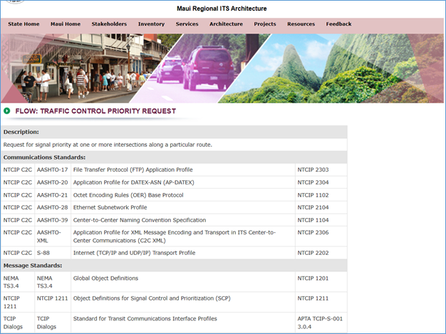
Transit Signal Priority Project ITS Standards
The standards that are identified in the architecture are only a starting point for the project design specification. Typically, only a subset of the identified standards will actually be used in the project and substantial detail must be included in the specification to identify the portions of the standard that are relevant to the particular procurement.
Several
resources describe how to specify ITS standards requirements for ITS
procurements. The ITS Standards Program web site includes the most current
information on ITS standards, including available deployment resources (http://www.standards.its.dot.gov).
The Communications View of the ARC-IT website also has
links to information concerning how the architecture information flows are
mapped to communications solutions.
The specification of applicable ITS standards is a required part of the
Systems Engineering Analysis as specified in the Regulation/Policy, per
CFR940.11(c)6.
Project ITS Architecture Use in Project Design
A project ITS architecture defined in SET-IT can provide additional details to support project design, beyond the information contained in a regional ITS architecture. The additional information includes:
- Customized service package diagrams
- Project interconnect summary diagrams
- Detailed standards communications representations
The customized service package diagrams contained in SET-IT provide a diagrammatic
view of a project similar to the service package diagrams in ARC-IT. This
diagrammatic view includes additional details beyond the definition of the
project architecture contained in RAD-IT. An example of the Queue Warning
Service Package diagram from the Sample SET-IT project is shown in the figure
below. Note that the diagram includes functional objects mapped to each of the
project elements. Also included are key human interfaces that are relevant to
the project, but are not included in a regional ITS architecture view of
projects.
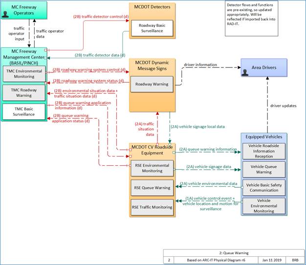
Sample Project Service Package Diagram
Note that the diagram provides a detailed set of information about each information flow that can be used to inform project design. This information includes indications of time context, spatial context, cardinality (one-to-one unicast, one-to-many broadcast, etc.), control, and security. This information can be found in the Shape Properties when an information flow is selected on the diagram in SET-IT. Much of the information is shown in the diagram in the way the information flows are drawn. The figure below shows a portion of the "Legend" from ARC-IT and SET-IT that indicates the meaning of the details of color and style of the information flows on the diagram.
ARC-IT Physical Information Flow Characteristics Legend
|
Topic |
Description |
|
|
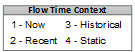
Flow Time Context is represented as a number to the left of the flow name. This indicates the time sensitivity of the data contained within the information flow. The values are "Now", "Recent", "Historical", or "Static" for data that never or rarely ever changes. |
|
|
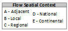
Flow Spatial Context is represented by a letter to the left of the flow name. This indicates the spatial relevance of the data contained within the information flow. The values are "Adjacent", "Local", "Regional", "National", or "Continental". |
|
|
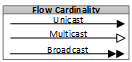
Flow Cardinality shows whether a flow is unicast (sent to one destination), multicast (sent to multiple addressees), or broadcast (sent to anyone with the right equipment). It is represented by the arrowhead – single, closed; single, open; or double, closed. |
|
|
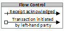
A crossing line at the flow source indicates whether an information flow is acknowledged. Flows that are part of a transaction initiated by one side or the other are shown with a white box on the side that initiates the transaction. |
|
|
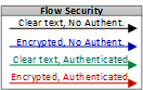
Flow Security is used to indicate what mechanisms should be in place in order for the information to get to its destination securely and in support of the overall security and privacy requirements for the system and its users. Black indicates 'clear' or no security specified; Blue indicates it should be encrypted but the sender does not have to be authenticated as the source of the message; Green indicates the information can be sent without encryption but the sender should be authenticated; Red indicates flows that require both encryption of the information and authentication of the source. These characteristics are based on a Federal Information Processing Standard (FIPS) standard known as FIPS-199 that evaluates confidentiality, integrity, and availability requirements for each triple. |
The second key type of information contained in SET-IT relates to the communications solution and the standards that can be used to implement the information exchanges that are part of the project. SET-IT contains detailed information (derived from ARC-IT) regarding the communications stacks that can provide the basis for a communications solution for each information flow. The stacks provide the best-known options for implementing each of the information flows. These may not be complete solutions, but they provide the best current solutions available (from an industry standards standpoint). The figure below shows an example communications stack for the flow vehicle location and motion for surveillance from Equipped Vehicles to the fictitious Marinara County Department of Transportation (MCDOT) Connected Vehicle (CV) Roadside Equipment. Note that this diagram shows the communications layers as well as the management and security protocols that should be provided to implement the interface.
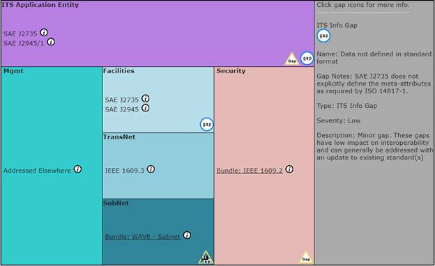
Communications Stack from Sample Project
An interface specification, which forms a part of project design, can be defined for any implementation, using these stacks and standards as the basis for that specification. In some cases, the specification may be quite simple, as the standards in question offer necessary definitions of dialogs, messages and data elements. In other cases, the specification will have to describe a great deal more, depending on the availability of necessary information.
Regional ITS Architecture Use Challenges and Solutions
Regions may need to address several challenges if the regional ITS architecture is to be used effectively to support project development. Across the country, regions are each encountering the same challenges and best practices are beginning to emerge that will encourage beneficial use of the architecture. Six challenges and their corresponding solutions are described below.

Challenge 1: While architecture maintenance responsibilities normally rest with a single agency, many agencies in a region are Project Sponsors that will need to use the architecture.
Solution: If it is to be used, the regional ITS architecture must be readily available to all Project Sponsors in the region. The latest version of the architecture should be available in a location readily accessible to all Project Team members. An architecture web page that provides access to the latest architecture information and resources is ideal. The form of the regional ITS architecture documentation should allow easy cut-and-paste into project documentation.
Challenge 2: Each of these Project Sponsor agencies has its own development process that must be adapted to use the regional ITS architecture if architecture use is to be systematic in the region.
Solution: The points at which the architecture should be used in project development should be formally documented for the state or region. In particular, an early checkpoint should be identified where the Project Team should have considered the architecture as the project scope is established so that integration opportunities are considered for each ITS project. A later checkpoint should be established where the Project Team should have verified that the as-designed project is consistent with the architecture and identified any regional ITS architecture changes that would be required to achieve this consistency.
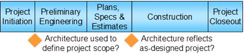
Example Architecture Use Checkpoints
The FHWA/FTA Division Office can assist project teams with defining these points in the process, integrating architecture use requirements with existing federal oversight requirements. Such top-down inclusion is an effective way to ensure systematic architecture use by all Project Sponsors in the region.
Challenge 3: The Project Manager and Project Team may have little or no experience with the regional ITS architecture. While the architecture development process is inclusive, smaller agencies may not have participated, and only a few individuals from participating agencies actually develop expertise with the architecture. Staff turnover can further dilute architecture expertise over time.
Solution: Although not everyone will be an architecture expert, at least one member of every Project Team must be able to effectively use the architecture. If the Project Team does not have this expertise, then technical assistance should be provided by the Architecture Maintainer, FHWA/FTA Division office, or another resource to identify the relevant portion of the architecture for the project. To facilitate architecture use, the region should make the architecture as easy to use as possible, document instructions for use in project implementation, and make technical assistance and training available to Project Teams.
The architecture documentation should be reviewed with a critical eye towards ease of use by Project Teams and revised as necessary to better support this critical use. Regions may find that their architecture is technically sound but should be revised so that it can be more easily used by Project Teams. In particular, it should be easy for users to navigate from one part of the architecture documentation (e.g., a particular inventory element) to other related parts (e.g., functional requirements, stakeholders, and interfaces).
 The
architecture should be supported by a roadmap for architecture use that can be
used by each Project Team. The roadmap for architecture use includes
step-by-step instructions for how the region's architecture documentation
should be used for project development.
The
architecture should be supported by a roadmap for architecture use that can be
used by each Project Team. The roadmap for architecture use includes
step-by-step instructions for how the region's architecture documentation
should be used for project development.
RAD-IT can be used to identify the portion of the regional ITS architecture that is included in a project, if the Project Team has access to the tool and is familiar with its use. While this is an excellent way to use the architecture, it is unlikely that every Project Team will have access to the RAD-IT software or be able to use it without some training.
This is where having the relevant connection from the Regional ITS Architecture to the project readily available in a web-based version of the architecture.
 Ease
of use should be coupled with an effective technical assistance program that
allows Project Teams to get the assistance that they need when they have a question
about architecture use. As technical assistance is requested and provided, it
is a good idea to continue to enhance the documentation available to every
Project Team with a set of frequently asked questions and answers that can
further facilitate future use.
Ease
of use should be coupled with an effective technical assistance program that
allows Project Teams to get the assistance that they need when they have a question
about architecture use. As technical assistance is requested and provided, it
is a good idea to continue to enhance the documentation available to every
Project Team with a set of frequently asked questions and answers that can
further facilitate future use.
Larger agencies should consider having an ITS specialist that can participate on ITS-related Project Teams and support architecture use as well as appropriate application of the systems engineering process and ITS standards. The ITS specialist becomes another specialist in the range of environmental, legal, and technical experts that are included on the Project Team, depending on the type of project.
Training in the region's ITS architecture, with focus on how to use the regional ITS architecture, should be available to Project Sponsors. The architecture use sections on the ARC-IT website and the online training courses available on the ARC-IT website include general information on architecture use that could be used as a starting point and tailored to focus on the region's architecture and ITS project development process.
To ensure expertise by consultant members of the Team, include RFP requirements for knowledge/experience with regional ITS architecture and its use in ITS project procurements.
Challenge 4: ITS projects are location specific and the regional ITS architecture is normally defined at a higher level. For example, many different projects may implement field equipment that is generally represented with a single inventory element in the regional ITS architecture as shown in the comparison of Washington State DOT regional ITS architecture inventory elements with Washington State DOT transportation projects. As shown, there are many projects that are implementing transportation improvements in the region covered by the two WSDOT field equipment elements.
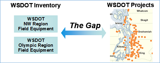
Architecture and Location-Specific Projects
Solution: In order to effectively use the architecture, the Project Team must bridge the gap between the higher-level regional ITS architecture and the relatively specific definition of a particular project. The different levels of abstraction are a potential stumbling block that should be addressed in the region's guidance for architecture use. For example, the project block diagram in a concept of operations may be more specific than what is represented in the regional ITS architecture, but still traceable to the regional ITS architecture.
 While
it is sometimes beneficial, you should proceed with caution when adding detail
to your regional ITS architecture so that it more precisely depicts individual
projects. For example, a city may deploy field equipment with ten different projects
over the course of several years. It is probably a mistake to include ten
different inventory elements in the regional ITS architecture that specifically
represent the equipment in each anticipated project. This would add too much
detail to the regional ITS architecture and make it more difficult to maintain.
But listing the ten projects separately in the architecture and mapping each to
the same service packages can provide a good link from the general to the
specific implementations.
While
it is sometimes beneficial, you should proceed with caution when adding detail
to your regional ITS architecture so that it more precisely depicts individual
projects. For example, a city may deploy field equipment with ten different projects
over the course of several years. It is probably a mistake to include ten
different inventory elements in the regional ITS architecture that specifically
represent the equipment in each anticipated project. This would add too much
detail to the regional ITS architecture and make it more difficult to maintain.
But listing the ten projects separately in the architecture and mapping each to
the same service packages can provide a good link from the general to the
specific implementations.
Challenge 5: Some ITS projects do not use the Highway Trust Fund and are not subject to the Regulation/Policy requirements. Projects developed exclusively with state or local funds and projects developed by non-transportation agencies (e.g., public safety agencies) fall into this category. For these projects, use of the architecture is strictly voluntary and can only be motivated by the potential benefits of use.
Solution: Information on the benefits of architecture use should be available to every project sponsor, not only those who sponsor projects that use the Highway Trust Fund. Some agencies, such as Virginia DOT, have developed a user guide that encourages architecture use for ITS projects, whether or not Highway Trust Funds are used. To coordinate public safety projects, the San Diego Association of Governments (SANDAG), the San Diego MPO, has established a public safety committee that coordinates planning for public safety integration projects with SANDAG. The architecture maintenance activity should periodically update the architecture to reflect other ITS projects that have been implemented so that the architecture continues to accurately reflect ITS implementation in the region.
Challenge 6: Some common projects that are categorized as ITS, like signal synchronization projects, impact only a single agency system and have lesser need to use the regional ITS architecture.
Solution: The purpose of the architecture use and systems engineering analysis requirements for ITS projects is to reduce technical risk and increase the likelihood of project success. Since the inherent risk in an ITS project varies significantly depending on the nature of the project, the Regulation/Policy allows the systems engineering analysis to be tailored commensurate with project scope. Projects that will benefit most from architecture use include:
- Multi-modal or multi-jurisdictional projects that connect systems from different agencies.
- New system developments that must consider future integration requirements.
Projects that are inherently limited in scope will benefit less from architecture use, such as:
- Installation of isolated rural traffic signals and other projects that have no reasonable opportunity for future integration
- System expansions that add no new interfaces and no new functionality (e.g., adding additional CCTV cameras to an existing system)
- Projects that enhance current system operation, but add no new interfaces or functionality (e.g., signal synchronization projects)
There is some potential benefit from architecture use on even the simplest ITS projects. For example, signal synchronization projects may benefit from architecture use in regions where integration of adjacent traffic signal systems is planned. The FHWA/FTA Division Office determines how the Regulation/Policy should be applied to different types of ITS projects in the region. For example, the California Division Office has established oversight procedures that require architecture use for all ITS projects, but only require direct oversight for higher risk "major" ITS projects. Some regions have established graduated processes where more detailed architecture use is suggested for more complex projects. An early project initiation checkpoint should include information about the project that allows project type and complexity to be determined so appropriate architecture use and systems engineering analysis processes can be defined.